Five hundred-meter aperture spherical radio telescope (FAST) is a multi-disciplinary basic research platform that is used for a wide range of astronomy research. Currently, narrow-band multi-beam feed are primarily employed for observation. The development of ultra-wide broadband feed system is beneficial for covering more scientific objectives, while also giving full play to the advantages of the FAST huge reception area in wider frequency band. This paper focuses on the 0.5-3.3GHz feed design, which has better than 10 dB simulated return loss across the bandwidth with the method of using fitting curves and dielectric loading and adding corrugated structures to improve the performance of quad ridge flared horn (QRFH). A centrally positioned PTFE dielectric rod regulates electromagnetic wave phase velocity, enhancing radiation directivity and main lobe symmetry. The dielectric rod is formed by two concentric layers with the same dielectric constant but different structures. The outer layer is evenly slotted to reduce its dielectric constant. The addition of the above technical means ensures the symmetry of the E-plane and H-plane far-field patterns, making the aperture efficiency of the feed relatively balanced over 6.6:1 bandwidth. This kind of feed is designed with an emphasis on performance, ease of tuning and manufacturability compared to the case of multi-layer dielectric rods.
This is an Open Access article, distributed under the terms of the Creative Commons Attribution 4.0 International License (http://creativecommons.org/licenses/by/4.0/), which permits unrestricted use, distribution and reproduction in any medium or format, provided the original work is properly cited.
The Five hundred-meter Aperture Spherical Radio Telescope (FAST) is national facility available for carrying out astronomical and astrophysical studies. It is the largest single-aperture radio telescope in the world with aperture of 500m diameter. The 19 beam receiver, as the main observation instrument, covers the frequency range of 1.05-1.45GHz (e.g.,
[1]
Jiang, P., Tang, N.-Y., Hou, L.-G., Liu, M.-T., Krčo, M., Qian, L, et al. The fundamental performance of FAST with 19-beam receiver at L band. Research in Astronomy and Astrophysics, 2020, 20(5), 064.
). More than 1000 pulsar have been confirmed as new pulsars. Now it is necessary to develop a set of ultra-wide broadband receivers with frequency band coverage of at least 0.5-3.3GHz to meet the requirement of covering multiple scientific objectives on a single platform.
In the field of radio astronomy, increasing the instantaneous bandwidth of the receiver system is beneficial. A larger bandwidth allows for increased sensitivity to broadband phenomena such as pulsars. The bandwidth of receiver systems based on reflector structures is often limited by the feed structure. Consequently there has been much interest in the development of multi-octave feed systems capable of achieving performance comparable to that of their conventional narrow band counterparts, just like corrugated horns. Several types of ultra-wideband feed have been developed. Several representative ones are the Eleven feed (e.g.,
[2]
Rikard Olsson; P-S Kildal; Sander Weinreb. The eleven antenna: a compact low-profile decade bandwidth dual polarized feed for reflector antennas, Antennas and Propagation, IEEE Transactions on. February 2006, 54(2): 368-375.
P -S Kildal; Jian Yang; Y. Karandikar; N. Wadefalk; M. Pantaleev; L. Helldner. Development of a coolable 2-14 GHz eleven feed for future radio telescopes for SKA Application. 2009. ICEAA. International Conference on, September 2009; Pages 545-547.
Jian Yang; P-S Kildal; Miroslav Pantaleev. Design of Compact Dual-Polarized 1.2–10 GHz Eleven Feed for Decade Bandwidth Radio Telescopes, IEEE Transactions on Antennas and Propagation, Vol. 60, No. 5, May 2012; 2110-2117.
G. Cortes-Medellin. Non-planar quasi-self-complementary ultra-wideband feed antenna. Antennas and propagation. IEEE Transactions on, Antennas and Propagation, IEEE Transactions on. June 2011, 59(6): 1935-1944.
Leeuwen J V, Team T A .The Allen Telescope Array: The First Widefield, Panchromatic, Snapshot Radio Camera for Radio Astronomy and SETI [J]. Proceedings of the IEEE, 2009, 97(8):1438-1447.
A. Akgiray; S. Weinreb; W. Imbriale. Design and measurements of dual polarized wideband constant beam-width quadru-ple-ridged flared horn. In Antennas and Propagation (APSURSI), 2011 IEEE International Symposium on, July 2011, Pages 1135-1138.
A kgiray; A., Weinreb. S. Ultra-wideband square and circular quad-ridge horns with near constant beam-width. IEEE Inter-national Conference on Ultra-wideband (ICUWB), 2012.
Akgiray A, Weinreb S, Imbriale W A, et al.Circular Quadruple-Ridged Flared Horn Achieving Near-Constant Beamwidth Over Multi-octave Bandwidth: Design and Measurements [J]. IEEE Transactions on Antennas and Propagation, 2013, 61(3):1099-1108.
) etc. The Eleven feed and QSC feed can be seen as a reversed logarithmic periodic antenna placed on a reflecting plate. This type of feed has a wide frequency band and relatively stable phase center, but poor return loss and cross polarization, as well as complex feed line systems. The ATA feed is the conventional logarithmic periodic antenna with continuous frequency coverage over 0.5–10 GHz and the phase center shifted along the axis of symmetry with frequency changes. It is more suitable for long focal lengths such as dual reflector antennas. Quad-ridged flare horns can exhibit low loss and a high return loss. However, they often suffer from a narrowing beam at high frequencies and asymmetry in the beam between the E and H planes. Another promising technology for broadband feed design is dielectrically loaded quad ridged flare horn with a corrugated skirt (e.g.,
[10]
Dunning A; Bowen M; et al. An ultra-wideband dielectrically loaded quad-ridged feed horn for radio astronomy. IEEE-APS Topic Conference. Turin, Italy: IEEE, 2015.
). This kind of feed can achieve a near constant beam width over a 6:1 bandwidth. The feed accepts two linear polarizations which are differentially fed.
2. Materials and Methods
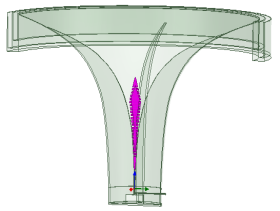
The primary objective of this feed horn design is to achieve near constant beam-width and high aperture efficiency across the frequency range of 0.5GHz to 3.3GHz for the FAST radio telescope, while minimizing performance trade-offs. The feed horn consists of coaxial line fed quad ridged structure with a central dielectric rod and choke groove. This kind of feed is one type of ultra-wideband Dielectrically Loaded Quad-ridged Flare Horn (hereinafter referred to as DLQRFH). Figure 1 displays across section of a HFSS model of the feed.
As shown in the Figure 1, the entire feed is composed of a square reflection cavity, two excitation probes, four ridge plates, a spindle shape dielectric rod, and choke groove from bottom to top. Two probes are installed orthogonally on the excitation circular waveguide, with the inner-conductors inserted perpendicular to each other into the opposite ridge plate. There is a deep hole at the connection between the ridge plate and the probe, which plays a good impedance matching role.
Due to the capacitance at the edge of the ridge, the cutoff frequency of the main mode TE11 in the ridged waveguide is lower than that of a circular waveguide of the same size, while the cutoff frequency of Higher-Order Modes is higher than that of a circular waveguide, resulting in a wider bandwidth of the ridged waveguide (e.g.,
[11]
Chen T S. Calculation of the Parameters of Ridge Waveguides. Ire Transactions on Microwave Theory & Techniques. 2003, 5(1): 12-17.
). Furthermore, spacing of ridges to each other and ridge thickness are important factors determining the nominal input impedance of the quad-ridge horn. In particular, bigger ridge-to-ridge gap near the feed point implies higher input impedance and vice versa. This is analogous to a distributed transmission line modeled with series inductance and shunt capacitance per unit length (e.g.,
[12]
Sun W, Balanis C A .Analysis and design of quadruple-ridged waveguides [J]. IEEE Transactions on Microwave Theory & Techniques, 1994, 42(12):2201-2207.
). Increased ridge-to-ridge gap implies decreased shunt capacitance and thus, the nominal impedance increases.
Ridge profile transforms the 50 Ohm input impedance to 377 Ohm free-space impedance at the horn aperture. The quadruple-ridged configuration consists of two sets of symmetrically distributed ridges, typically arranged orthogonally to enable dual-polarized operation. Bandwidth expansion (0.5–3.3 GHz) and impedance matching improvements are achieved by optimizing geometric parameters such as ridge gap and ridge flare angle.
An embedded coaxial feed port within the ridged waveguide allows multi-directional flexible excitation by adjusting feed point positions through-holes on ridges. As such, appropriate profile selection is paramount to obtaining good return loss performance. Various different profiles have been reported in literature, for example, elliptical, exponential, linear, Gaussian, Fermi-like, some of which were evaluated as part of the design process (e.g.,
[13]
Granet. C. Profile options for feed horn design. IEEE Asia-Pacific Microwave Conference Proceedings, Sydney, NEW, Australia, 2000: 1448-1451.
). The best results have, so far, been achieved by the exponential profile which is the profile used in this work, namely.
X(z)=Aeγz+Bz+C(1)
Which, A and 𝛾 are related to the size of the mouth radius, while B and C mainly affect the trend of curve changes. This article mainly uses this curve as a reference to fit the curve and make local adjustments during the simulation process until a satisfactory result is achieved.
The application of dielectric rods in broadband antennas is beneficial to control the beam width and phase center stability of far-field directional patterns (e.g.,
[14]
Chen C C, Rao K R, Lee R .A new ultrawide-bandwidth dielectric-rod antenna for ground-penetrating radar applications [J]. IEEE Transactions on Antennas & Propagation, 2003, 51(3): 371-377.
Liu, C.-W., & Chen, C.-C.. A UWB Three-Layer Dielectric Rod Antenna With Constant Gain, Pattern and Phase Center. IEEE Transactions on Antennas and Propagation, 2012, 60(10), 4500–4508.
). A centrally positioned polytetrafluoroethylene (PTFE) dielectric rod (εr ≈ 2.1, tanδ < 0.0002) regulates electromagnetic wave phase velocity, enhancing radiation directivity and main lobe symmetry. The dielectric rod is formed by two concentric layers with the same dielectric constant but different structures. The outer layer is evenly slotted to reduce its dielectric constant. The purpose of this structure is to approximate a graded dielectric configuration with a high-permittivity core and low-permittivity periphery.
At low frequencies (below 1.7 GHz), the beam pattern is predominantly governed by the annular choke grooves, which suppress edge diffraction and stabilize side-lobe levels. At high frequencies (above 2 GHz), the beam-width is primarily determined by the PTFE dielectric rod, which regulates phase velocity distribution and enhances directivity.
This design achieves frequency adaptive beam control by leveraging geometry-dependent dominance of choke grooves (low-frequency diffraction management) and dielectric phase correction (high-frequency focusing).
3. Results
The horn model simulation is performed in HFSS, with the radiation boundary, with final meshes of about 257791 tetrahedral, and with a good convergence history. For parametric optimization, the interpolating sweep is used; all final results have been controlled using discrete frequency sweep. The simulated results of S parameter and far field pattern for the design model are as follows.
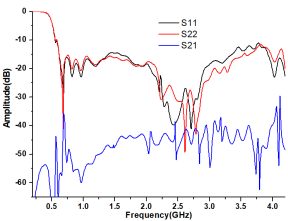
3.1. S Parameter
The simulation results of S parameter for the UWLF are shown in the Figure 2. The return loss of two ports is better than 15dB at most frequency points. The isolation is better than 40dB throughout the entire frequency band.
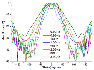
Figure 4. H-plane Far field pattern for the DLQRFH.
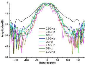
The reason for the significant difference in the far field patterns of some frequency point is mainly due to the discontinuity caused by the influence of the ridge. The field distribution on its aperture surface is multimode, and the mode ratio also changes with frequency.
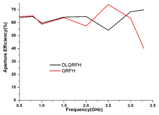
3.3. Aperture Efficiency
By importing the far-field pattern of the feed into CST and combining it with the reflector antenna (f/D=0.4611), the gain of each frequency point can be calculated. By comparing it with the theoretical gain obtained by the physical aperture of the reflector antenna, the aperture efficiency of different frequency points can be obtained. We calculated the aperture efficiency results of the same structure and ridge curve with or without dielectrics loading and choke groove. The results are shown in the Figure 5.
Figure 5. Aperture efficiency of the DLQRFH and QRFH without dielectrics and choke groove.
4. Discussion
The simulation results show that the S-parameter performance and the rotational symmetry of the far field pattern for this kind of feed is good. However, the beam constant needs to be improved. This leads to low efficiency at some frequency points. As mentioned earlier, the shape of the ridge will affect the distribution of the electric field on the aperture surface, and the changes in the horn wall will also affect the stability of the far-field pattern.
5. Conclusions
The present paper has introduced and discussed the design and simulation of the ultra-wideband Dielectrically Loaded Quad Ridged Flare Horn with a corrugated skirt (DLQRFH) for FAST. The simulation results illustrate that the performance of return loss and aperture efficiency for this kind of feed has improved significantly compared to traditional QRFH. It also can be seen that the performance indicators can meet the design requirements, proving that this method is feasible. In order to further expand the bandwidth characteristics of the antenna and improve its electrical performance, the next step can be to use optimization design and simulation experiments to improve the antenna design.
Abbreviations
FAST
Five Hundred-meter Aperture Spherical Radio Telescope
QSC
Quasi-self-complementary
ATA
Allen Telescope Array
QRFH
Quad Ridge Flared Horn
DLQRFH
Dielectrically Loaded Quad-Ridged Flared Horn
HFSS
High Frequency Structure Simulation
CST
Computer Simulation Technology
Acknowledgments
This work is supported by the National Natural Science Foundation of China (Grant No. 12273072) and Qiannan Prefecture Science and Technology Projects (No. QNKHSZ [2024]10)and Guizhou Province High-level Talent Program (No.QKHPTRC-GCC[2022]003-1) and Guizhou Provincial Scientific and Technological Program The Postdoctoral Research Station of the Guizhou Radio Astronomical Observatory. (No.QKHPTRC{2021]Postdoctoral Research Station-001 .
Author Contributions
Jinglong Yu provided the idea, and used software for simulation analysis. Hongfei Liu provided investigation support and funding resources. Jianbin Li reviewed and edited the manuscript. All the authors read and approved the final manuscript.
Data Availability Statement
The data supporting the outcome of this research work has been reported in this manuscript.
Conflicts of Interest
The authors declare no conflicts of interest.
References
[1]
Jiang, P., Tang, N.-Y., Hou, L.-G., Liu, M.-T., Krčo, M., Qian, L, et al. The fundamental performance of FAST with 19-beam receiver at L band. Research in Astronomy and Astrophysics, 2020, 20(5), 064.
Rikard Olsson; P-S Kildal; Sander Weinreb. The eleven antenna: a compact low-profile decade bandwidth dual polarized feed for reflector antennas, Antennas and Propagation, IEEE Transactions on. February 2006, 54(2): 368-375.
P -S Kildal; Jian Yang; Y. Karandikar; N. Wadefalk; M. Pantaleev; L. Helldner. Development of a coolable 2-14 GHz eleven feed for future radio telescopes for SKA Application. 2009. ICEAA. International Conference on, September 2009; Pages 545-547.
Jian Yang; P-S Kildal; Miroslav Pantaleev. Design of Compact Dual-Polarized 1.2–10 GHz Eleven Feed for Decade Bandwidth Radio Telescopes, IEEE Transactions on Antennas and Propagation, Vol. 60, No. 5, May 2012; 2110-2117.
G. Cortes-Medellin. Non-planar quasi-self-complementary ultra-wideband feed antenna. Antennas and propagation. IEEE Transactions on, Antennas and Propagation, IEEE Transactions on. June 2011, 59(6): 1935-1944.
Leeuwen J V, Team T A .The Allen Telescope Array: The First Widefield, Panchromatic, Snapshot Radio Camera for Radio Astronomy and SETI [J]. Proceedings of the IEEE, 2009, 97(8):1438-1447.
A. Akgiray; S. Weinreb; W. Imbriale. Design and measurements of dual polarized wideband constant beam-width quadru-ple-ridged flared horn. In Antennas and Propagation (APSURSI), 2011 IEEE International Symposium on, July 2011, Pages 1135-1138.
A kgiray; A., Weinreb. S. Ultra-wideband square and circular quad-ridge horns with near constant beam-width. IEEE Inter-national Conference on Ultra-wideband (ICUWB), 2012.
Akgiray A, Weinreb S, Imbriale W A, et al.Circular Quadruple-Ridged Flared Horn Achieving Near-Constant Beamwidth Over Multi-octave Bandwidth: Design and Measurements [J]. IEEE Transactions on Antennas and Propagation, 2013, 61(3):1099-1108.
Dunning A; Bowen M; et al. An ultra-wideband dielectrically loaded quad-ridged feed horn for radio astronomy. IEEE-APS Topic Conference. Turin, Italy: IEEE, 2015.
Sun W, Balanis C A .Analysis and design of quadruple-ridged waveguides [J]. IEEE Transactions on Microwave Theory & Techniques, 1994, 42(12):2201-2207.
Chen C C, Rao K R, Lee R .A new ultrawide-bandwidth dielectric-rod antenna for ground-penetrating radar applications [J]. IEEE Transactions on Antennas & Propagation, 2003, 51(3): 371-377.
Liu, C.-W., & Chen, C.-C.. A UWB Three-Layer Dielectric Rod Antenna With Constant Gain, Pattern and Phase Center. IEEE Transactions on Antennas and Propagation, 2012, 60(10), 4500–4508.
Yu, J., Liu, H., Li, J. (2025). Design and Simulation of Dielectric Load Ultra-Wide Band Corrugated Feed for FAST. Science Discovery, 13(3), 46-50. https://doi.org/10.11648/j.sd.20251303.12
Yu, J.; Liu, H.; Li, J. Design and Simulation of Dielectric Load Ultra-Wide Band Corrugated Feed for FAST. Sci. Discov.2025, 13(3), 46-50. doi: 10.11648/j.sd.20251303.12
Yu J, Liu H, Li J. Design and Simulation of Dielectric Load Ultra-Wide Band Corrugated Feed for FAST. Sci Discov. 2025;13(3):46-50. doi: 10.11648/j.sd.20251303.12
@article{10.11648/j.sd.20251303.12,
  author = {Jinglong Yu and Hongfei Liu and Jianbin Li},
  title = {Design and Simulation of Dielectric Load Ultra-Wide Band Corrugated Feed for FAST
},
  journal = {Science Discovery},
  volume = {13},
  number = {3},
  pages = {46-50},
  doi = {10.11648/j.sd.20251303.12},
  url = {https://doi.org/10.11648/j.sd.20251303.12},
  eprint = {https://article.sciencepublishinggroup.com/pdf/10.11648.j.sd.20251303.12},
  abstract = {Five hundred-meter aperture spherical radio telescope (FAST) is a multi-disciplinary basic research platform that is used for a wide range of astronomy research. Currently, narrow-band multi-beam feed are primarily employed for observation. The development of ultra-wide broadband feed system is beneficial for covering more scientific objectives, while also giving full play to the advantages of the FAST huge reception area in wider frequency band. This paper focuses on the 0.5-3.3GHz feed design, which has better than 10 dB simulated return loss across the bandwidth with the method of using fitting curves and dielectric loading and adding corrugated structures to improve the performance of quad ridge flared horn (QRFH). A centrally positioned PTFE dielectric rod regulates electromagnetic wave phase velocity, enhancing radiation directivity and main lobe symmetry. The dielectric rod is formed by two concentric layers with the same dielectric constant but different structures. The outer layer is evenly slotted to reduce its dielectric constant. The addition of the above technical means ensures the symmetry of the E-plane and H-plane far-field patterns, making the aperture efficiency of the feed relatively balanced over 6.6:1 bandwidth. This kind of feed is designed with an emphasis on performance, ease of tuning and manufacturability compared to the case of multi-layer dielectric rods.
},
 year = {2025}
}
TY  - JOUR
T1  - Design and Simulation of Dielectric Load Ultra-Wide Band Corrugated Feed for FAST

AU  - Jinglong Yu
AU  - Hongfei Liu
AU  - Jianbin Li
Y1  - 2025/06/11
PY  - 2025
N1  - https://doi.org/10.11648/j.sd.20251303.12
DO  - 10.11648/j.sd.20251303.12
T2  - Science Discovery
JF  - Science Discovery
JO  - Science Discovery
SP  - 46
EP  - 50
PB  - Science Publishing Group
SN  - 2331-0650
UR  - https://doi.org/10.11648/j.sd.20251303.12
AB  - Five hundred-meter aperture spherical radio telescope (FAST) is a multi-disciplinary basic research platform that is used for a wide range of astronomy research. Currently, narrow-band multi-beam feed are primarily employed for observation. The development of ultra-wide broadband feed system is beneficial for covering more scientific objectives, while also giving full play to the advantages of the FAST huge reception area in wider frequency band. This paper focuses on the 0.5-3.3GHz feed design, which has better than 10 dB simulated return loss across the bandwidth with the method of using fitting curves and dielectric loading and adding corrugated structures to improve the performance of quad ridge flared horn (QRFH). A centrally positioned PTFE dielectric rod regulates electromagnetic wave phase velocity, enhancing radiation directivity and main lobe symmetry. The dielectric rod is formed by two concentric layers with the same dielectric constant but different structures. The outer layer is evenly slotted to reduce its dielectric constant. The addition of the above technical means ensures the symmetry of the E-plane and H-plane far-field patterns, making the aperture efficiency of the feed relatively balanced over 6.6:1 bandwidth. This kind of feed is designed with an emphasis on performance, ease of tuning and manufacturability compared to the case of multi-layer dielectric rods.

VL  - 13
IS  - 3
ER  -
National Astronomical Observatories, China Academicals of Science, Beijing, China; School of Astronomy and Space Science, University of China Academicals of Science, Beijing, China; Guizhou Radio Astronomical Observatory, Guizhou University, Guiyang, China
National Astronomical Observatories, China Academicals of Science, Beijing, China; School of Astronomy and Space Science, University of China Academicals of Science, Beijing, China
Yu, J., Liu, H., Li, J. (2025). Design and Simulation of Dielectric Load Ultra-Wide Band Corrugated Feed for FAST. Science Discovery, 13(3), 46-50. https://doi.org/10.11648/j.sd.20251303.12
Yu, J.; Liu, H.; Li, J. Design and Simulation of Dielectric Load Ultra-Wide Band Corrugated Feed for FAST. Sci. Discov.2025, 13(3), 46-50. doi: 10.11648/j.sd.20251303.12
Yu J, Liu H, Li J. Design and Simulation of Dielectric Load Ultra-Wide Band Corrugated Feed for FAST. Sci Discov. 2025;13(3):46-50. doi: 10.11648/j.sd.20251303.12
@article{10.11648/j.sd.20251303.12,
  author = {Jinglong Yu and Hongfei Liu and Jianbin Li},
  title = {Design and Simulation of Dielectric Load Ultra-Wide Band Corrugated Feed for FAST
},
  journal = {Science Discovery},
  volume = {13},
  number = {3},
  pages = {46-50},
  doi = {10.11648/j.sd.20251303.12},
  url = {https://doi.org/10.11648/j.sd.20251303.12},
  eprint = {https://article.sciencepublishinggroup.com/pdf/10.11648.j.sd.20251303.12},
  abstract = {Five hundred-meter aperture spherical radio telescope (FAST) is a multi-disciplinary basic research platform that is used for a wide range of astronomy research. Currently, narrow-band multi-beam feed are primarily employed for observation. The development of ultra-wide broadband feed system is beneficial for covering more scientific objectives, while also giving full play to the advantages of the FAST huge reception area in wider frequency band. This paper focuses on the 0.5-3.3GHz feed design, which has better than 10 dB simulated return loss across the bandwidth with the method of using fitting curves and dielectric loading and adding corrugated structures to improve the performance of quad ridge flared horn (QRFH). A centrally positioned PTFE dielectric rod regulates electromagnetic wave phase velocity, enhancing radiation directivity and main lobe symmetry. The dielectric rod is formed by two concentric layers with the same dielectric constant but different structures. The outer layer is evenly slotted to reduce its dielectric constant. The addition of the above technical means ensures the symmetry of the E-plane and H-plane far-field patterns, making the aperture efficiency of the feed relatively balanced over 6.6:1 bandwidth. This kind of feed is designed with an emphasis on performance, ease of tuning and manufacturability compared to the case of multi-layer dielectric rods.
},
 year = {2025}
}
TY  - JOUR
T1  - Design and Simulation of Dielectric Load Ultra-Wide Band Corrugated Feed for FAST

AU  - Jinglong Yu
AU  - Hongfei Liu
AU  - Jianbin Li
Y1  - 2025/06/11
PY  - 2025
N1  - https://doi.org/10.11648/j.sd.20251303.12
DO  - 10.11648/j.sd.20251303.12
T2  - Science Discovery
JF  - Science Discovery
JO  - Science Discovery
SP  - 46
EP  - 50
PB  - Science Publishing Group
SN  - 2331-0650
UR  - https://doi.org/10.11648/j.sd.20251303.12
AB  - Five hundred-meter aperture spherical radio telescope (FAST) is a multi-disciplinary basic research platform that is used for a wide range of astronomy research. Currently, narrow-band multi-beam feed are primarily employed for observation. The development of ultra-wide broadband feed system is beneficial for covering more scientific objectives, while also giving full play to the advantages of the FAST huge reception area in wider frequency band. This paper focuses on the 0.5-3.3GHz feed design, which has better than 10 dB simulated return loss across the bandwidth with the method of using fitting curves and dielectric loading and adding corrugated structures to improve the performance of quad ridge flared horn (QRFH). A centrally positioned PTFE dielectric rod regulates electromagnetic wave phase velocity, enhancing radiation directivity and main lobe symmetry. The dielectric rod is formed by two concentric layers with the same dielectric constant but different structures. The outer layer is evenly slotted to reduce its dielectric constant. The addition of the above technical means ensures the symmetry of the E-plane and H-plane far-field patterns, making the aperture efficiency of the feed relatively balanced over 6.6:1 bandwidth. This kind of feed is designed with an emphasis on performance, ease of tuning and manufacturability compared to the case of multi-layer dielectric rods.

VL  - 13
IS  - 3
ER  -